EDM Driller Automation - Lock Wire Holes
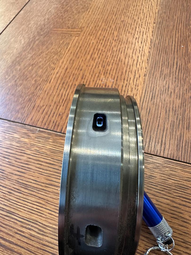
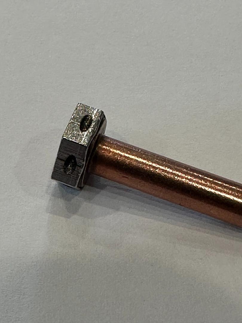
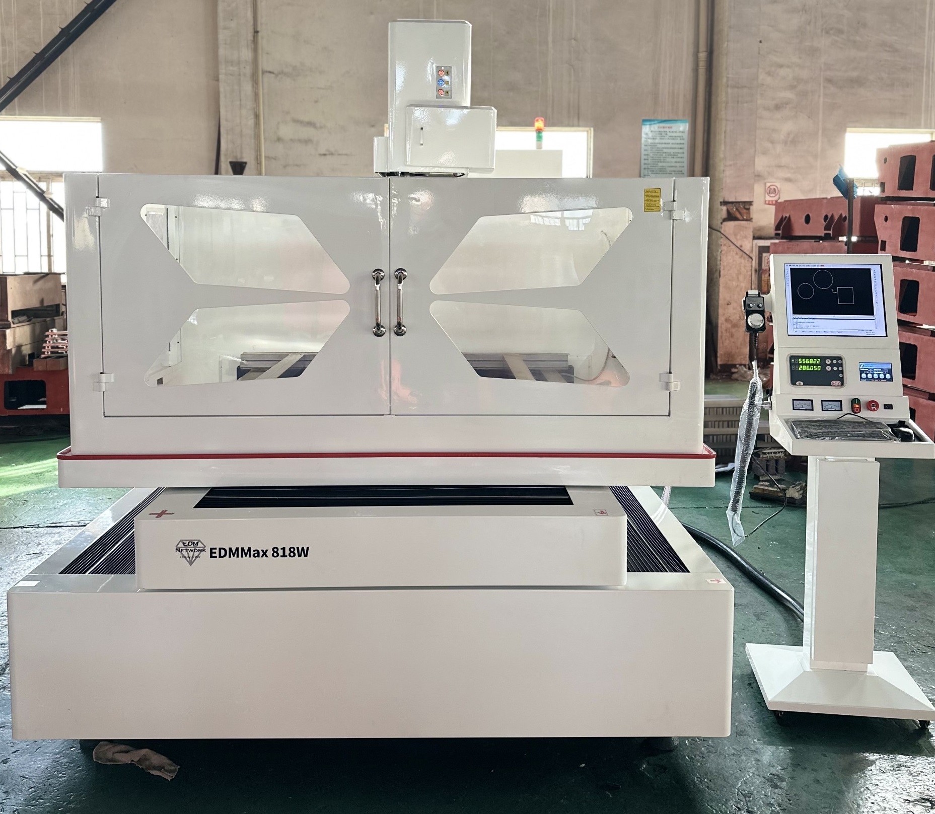
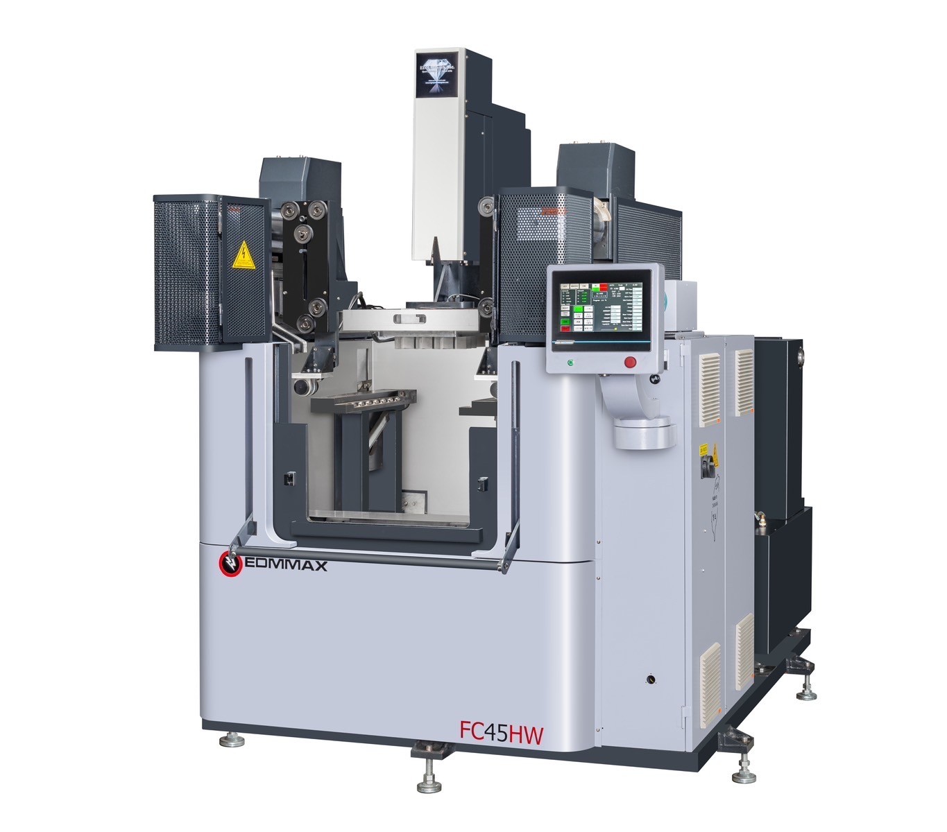
Automate lock wire hole drilling with EDM and Robotics. We offer complete systems to load, radially orient and then EDM drill hex heads, socket head cap screws, lock nuts and other fasteners. Lights out burr-free EDM drilling automation - affordably priced!